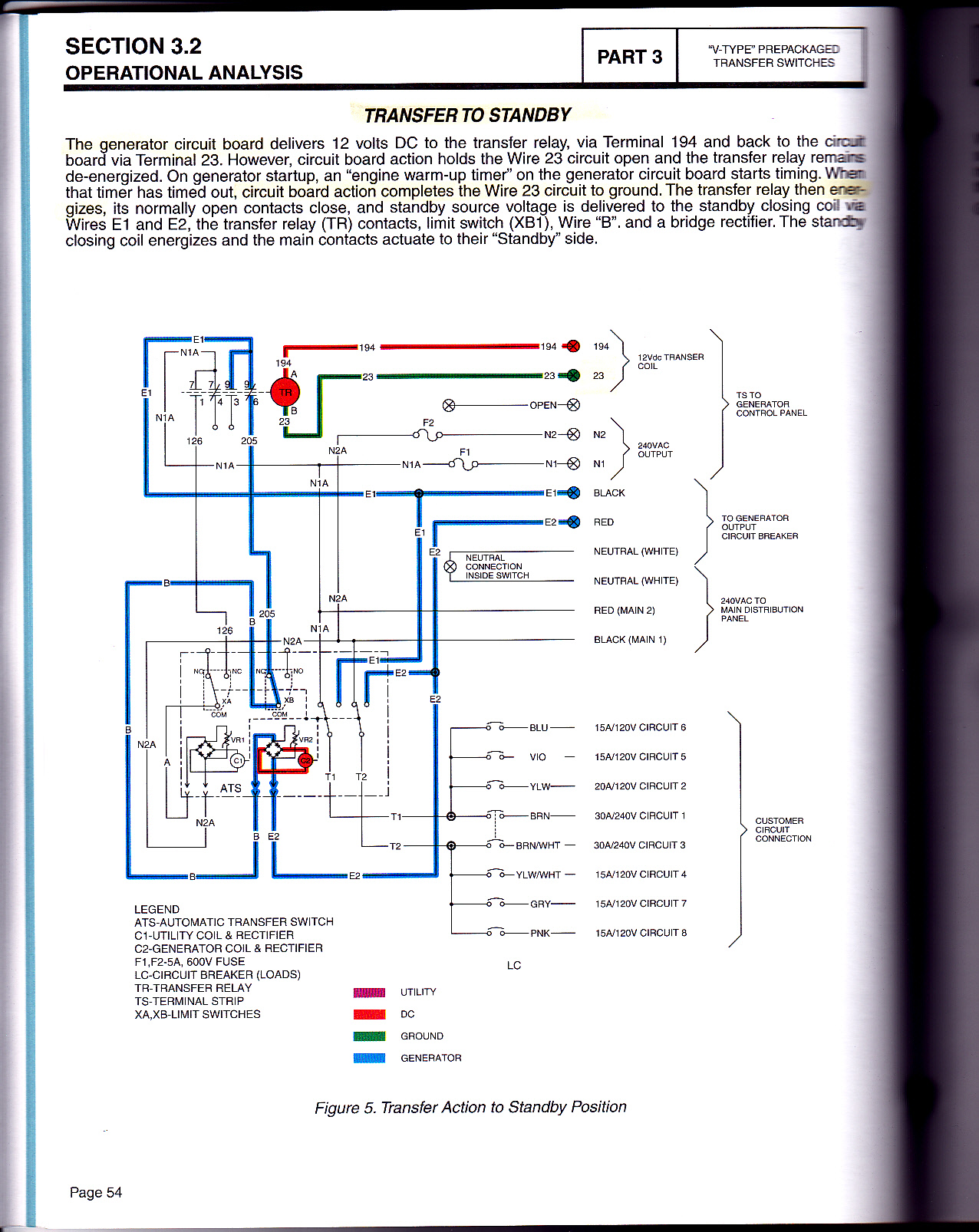
Transfer to Standby Sequence
RE: 10kw 2004 vintage (actually an SOP (Standard Operation Procedure)
This is controlled by the Generator control Board
The control board puts a + 12VDC on the Transfer Relay (Wire 194)
The Control board puts a GROUND on the Transfer Relay (Wire 23) when actually doing the transfer to the Generator. (See the Diagram)
NO TRANSFER usually means a bad Control board.
Things to check...............
When in Transfer Mode (Utility Power is OFF, either by killing the Power Company Main Breaker or by pulling the 2 cartridge fuses in the Transfer Switch) the Control board should put a ground on terminal 23 and cause the relay to energize. With a volt meter you should be able to read 12 VDC across wires 194(+) and 23(-). If there is NO voltage then the control board may be bad. If there is 12 VDC on this terminal pair, then the Control Transfer Relay may be bad.
